
![]()
2014 New | MPPT solar controllers | I series solar controllers | S series solar controllers | C Sereis Solar Controllers | V Series Solar Controllers | G Z Sereis Solar Controller
WaterProof Solar Controllers |
48V Solar Controllers | Dual Battery Controllers | Solar Controllers With LED drivers | Accessories | User Manual
Oversea Warehouse - Australia - United States - United Kingdom

 |
||
 |
 |
 |
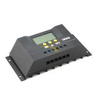
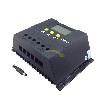
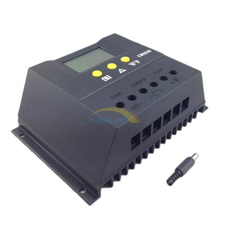
CM3024 CM3048 12V 24V 48V Solar Charge Controller with LCD display light and timer control
|
 |
|
 |
 |
 |
This 30A controller is a kind of intelligent, multi-purpose solar charge and discharge controller. The family use the fixed LCD display, with a very friendly interface; various control parameters can be flexibly set, fully meet your various application requirements.
Features:
>>Image of LCD graphic symbol
>>Simple button operation
>>Automatic Identification System Voltage level
>>Intelligent PWM charge mode
>>Automatic Temperature Compensation
>>Adjustable charge-discharge control parameters
>>Settable Operating mode of Load
>>Overload, Short Circuit Protection
>>Remote monitoring and control function (custom)
>>Battery reverse-discharge protection
>>Battery Low Voltage Disconnection (LVD)
>>Battery reverse connection protection
>>Accumulated function of charge and discharge Ampere hours
Installation
1. Ready tools and cables. Encourage you to matching the right cables. Ensure that the current density<4mm2 that is conductive to reducing the line voltage drop. Recommended: 60A with 20mm2 cable. Check weather the installation sitescompliance with the relevant safety requirements. Please avoid the damp, dusty, there is a place flammable, explosive and corrosive gases use the controller to install.
2. Install the controller into a fixed vertical plane. See section 5 of the pore size and pore spacing. In order to ensure a good thermal control conditions, please set aside each 10cm below the controller space.
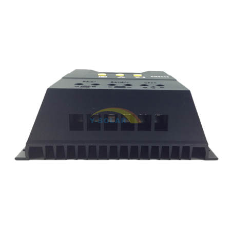
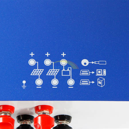
3. As shown on the right, connect the (1) Load, (2) Battery and (3) Solar Panel to the controller according to the order of (1) (2) (3). Pay attention to the load, battery, solar panel and controller of same polarity.
4. Put into the external temperature sensor on the left of the controller (probe port). The temperature sensor should be similar space with battery. (Otherwise, the controller will control the parameters of all wrong temperature compensation.)
5.If you have remote monitoring and control function, please insert one end of the included communication wire on the right of the controller (communication port), the other end to connect to The host computer.
Demolition: To prevent accidents, please order the demolition of solar panels, battery and load disconnect with controller.
Note:Battery polarity will not damage the controller, but you will have a load equipment security risks.
Specifications:
Model |
CM2024Z |
CM3024Z |
CM2048Z |
CM3048Z |
Rated Current |
20A |
30A |
20A |
30A |
Rated Voltage |
12V/24V |
48V |
||
Open Circuit Voltage of solar panel |
<=50V |
<=100V |
||
Low Voltage Disconnection(LVD) |
10.7V/21.4V |
42.8V |
||
Float Voltage |
13.8V/27.6V |
55.2V |
||
Low Voltage Reconnection(LVR) |
12.5V/25.0V |
50.0V |
||
No load loss |
<=30mA |
|||
Loop Voltage Drop |
<=170mV |
|||
Charging Mode |
PWM mode |
|||
Temperature Compensation |
-4mV/Cell/'C |
|||
Installation cable area. |
<=7#AWG (16mm2) |
|||
Operating Temperature |
-10'C--60'C |
|||
Storage temperature |
-30'C--70'C |
|||
Humidity requirements |
<=90%,no condensation |
|||
Size |
90 mmx188 mmx48 mm |
|||
Mounting hole spacing |
60 mmx178 mm --dia5 |
|||
weight |
360g |
|||
|
 |
|
 |
 |
 |
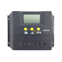
This 50A controller is a kind of intelligent, multi-purpose solar charge and discharge controller. The family use the fixed LCD display, with a very friendly interface; various control parameters can be flexibly set, fully meet your various application requirements.
Features:
Simple button operation
Intelligent PWM charge mode
Adjustable charge-discharge control parameters
Overload, Short Circuit Protection
Battery reverse-discharge protection
Battery reverse connection protection
Image of LCD graphic symbol
Automatic Identification System Voltage level
Automatic Temperature Compensation
Settable Operating mode of Load
Remote monitoring and control function (custom)
Battery Low Voltage Disconnection (LVD)
Accumulated function of charge and discharge Ampere hours
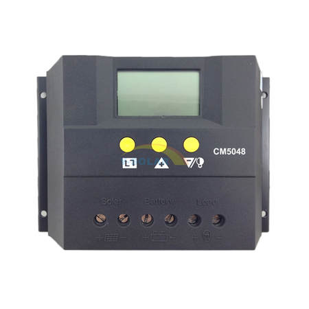
| Model | CM5024Z | CM5048 |
| Rated Current | 50A | |
| Rated Voltage | 12V/24V | 48V |
| Maximum Voltage of solar panel | 50V | 100V |
| Float Voltage | 13.7V/27.4V | 54.8V |
| Low Voltage Disconnection | 10.7V/21.4V | 42.8V |
| Low Voltage Reconnection | 12.6V/25.2V | 50.4V |
| No load loss | <30mA | |
| loop voltage drop | <200mV | |
| Charging Mode | PMW Mode | |
| Temperature Compensation | -4mV/Cell/℃ | |
Installation
① Get ready for tools and cables. Advising you to matching the right cables. Ensure that the current density <4A/mm2 that is conductive to reducing the line voltage drop. Recommendation: 30A with 10mm2 cables. Check whether the installation sites compliance with the relevant safety requirements. Please avoid the damp, dusty, there is a place flammable, explosive and corrosive gases use the controller to install.
② Install the controller into a fixed vertical plane. See section 5 of the pore size and pore spacing. In order to ensure a good thermal control conditions, please set aside each 10cm below the controller space.
③ As shown on the right, connect the (1) Load, (2) Battery and (3) Solar Panel to the controller according to the order of (1) (2) (3). Pay attention to the load, battery, solar panel and controller of same polarity.
④ Put the external temperature sensor into the left of the controller (probe port). The temperature sensor should be placed at the similar space of the battery. (Otherwise, the controller will control the parameters of all wrong temperature compensation.)
⑤ If you have remote monitoring and control function, please insert one end of the included communication wire on the right of the controller (communication port), the other end to connect to the host computer.
Demolition: To prevent accidents, please order the demolition of solar panels, battery and load disconnect with controller.
Note:Battery polarity will not damage the controller, but you will have a load equipment security risks.
Installtion cable area |
>3# AWG ( 25mm2 ) |
Operation temperature |
-20℃ ~ 50℃ |
storage temperature |
-30℃ ~ 70℃ |
Humidity requirement |
<90% , no condensation |
Size |
130mm*188mm*62mm |
Mounting hole spacing |
90 mm 178 mm -- 5 |
Weight |
590g |
CM60 60A Solar Charge Controller with LCD display light and timer control
|
|
|
|
|
|
This 60A controller is a kind of intelligent, multi-purpose solar charge and discharge controller. The family use the fixed LCD display, with a very friendly interface; various control parameters can be flexibly set, fully meet your various application requirements.
Features:
Simple button operation
Intelligent PWM charge mode
Adjustable charge-discharge control parameters
Overload, Short Circuit Protection
Battery reverse-discharge protection
Battery reverse connection protection
Image of LCD graphic symbol
Automatic Identification System Voltage level
Automatic Temperature Compensation
Settable Operating mode of Load
Remote monitoring and control function (custom)
Battery Low Voltage Disconnection (LVD)
Accumulated function of charge and discharge Ampere hours
| Model | CM6024Z | CM6048 |
| Rated Current | 60A | |
| Rated Voltage | 12V/24V | 48V |
| Maximum Voltage of solar panel | 50V | 100V |
| Float Voltage | 13.7V/27.4V | 54.8V |
| Low Voltage Disconnection | 10.7V/21.4V | 42.8V |
| Low Voltage Reconnection | 12.6V/25.2V | 50.4V |
| No load loss | <30mA | |
| loop voltage drop | <200mV | |
| Charging Mode | PMW Mode | |
| Temperature Compensation | -4mV/Cell/℃ | |
Installation
① Get ready for tools and cables. Advising you to matching the right cables. Ensure that the current density <4A/mm2 that is conductive to reducing the line voltage drop. Recommendation: 30A with 10mm2 cables. Check whether the installation sites compliance with the relevant safety requirements. Please avoid the damp, dusty, there is a place flammable, explosive and corrosive gases use the controller to install.
② Install the controller into a fixed vertical plane. See section 5 of the pore size and pore spacing. In order to ensure a good thermal control conditions, please set aside each 10cm below the controller space.
③ As shown on the right, connect the (1) Load, (2) Battery and (3) Solar Panel to the controller according to the order of (1) (2) (3). Pay attention to the load, battery, solar panel and controller of same polarity.
④ Put the external temperature sensor into the left of the controller (probe port). The temperature sensor should be placed at the similar space of the battery. (Otherwise, the controller will control the parameters of all wrong temperature compensation.)
⑤ If you have remote monitoring and control function, please insert one end of the included communication wire on the right of the controller (communication port), the other end to connect to the host computer.
Demolition: To prevent accidents, please order the demolition of solar panels, battery and load disconnect with controller.
Note:Battery polarity will not damage the controller, but you will have a load equipment security risks.
Installtion cable area |
>3# AWG ( 25mm2 ) |
Operation temperature |
-20℃ ~ 50℃ |
storage temperature |
-30℃ ~ 70℃ |
Humidity requirement |
<90% , no condensation |
Size |
130mm*188mm*62mm |
Mounting hole spacing |
90 mm 178 mm -- 5 |
Weight |
690g |
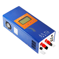
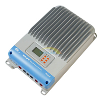
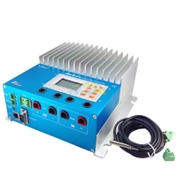
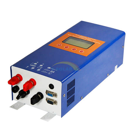
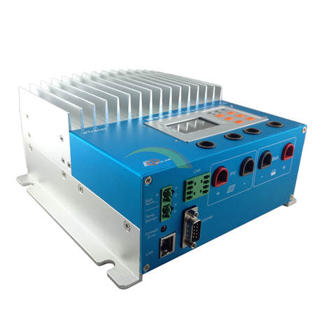
EMPPT-30 30A 12V 24V 48V Solar Charge Controller
Features
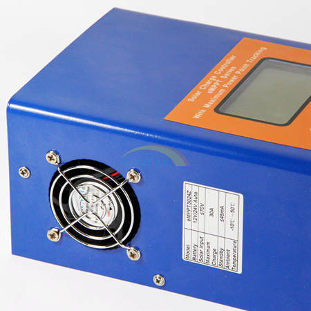
The product adopts DC/DC converting technology and MCU technology. It can adjust the working point of the solar panels array intelligently to make the solar panels array realize the maximum power output. When the external condition changes, eMPPT controller bases on the MCU theory to track the maximum working point of the solar panels, this can improve the using efficiency of the solar panels and decrease the solar generating cost. Compared with average solar charge controllers, eMPPT can improve the output efficiency of the solar panels by 5% to 30 %( the output increasing proportion affected by the factors such as the attribute of the solar panels, environmental temperature and lighting conditions). The product adopts in big screen lattice LCD, and uses the vivid icons to indicate the parameters. It has concise and vivid interface. The product is wall mounting installation. Please refer to chapter 2.1 for the installing dimensions.
|
 |
|
 |
 |
 |
Product functions
|
Functions |
instruction |
1 |
maximum power point tracking |
Adopting DC/DC converting technology and MCU technology to realize the maximum output of the solar panels |
2 |
battery reversed connection protection |
Battery polarity connecting to the controller reversely (under the condition not connecting solar panels) will not cause damage to controller. It can work normally after connecting right. |
3 |
Anti-battery reverse discharge |
When solar panels voltage is less than battery voltage, the battery will not charge to the solar panels array. |
4 |
Anti-solar panels reverse connection |
Solar panels array polarity connecting to the controller reversely will not cause damage to controller. It can work normally after connecting right |
5 |
three-stage charge control |
Bulk Absorption Float |
6 |
float charging voltage adjustable |
The users can adjust the float charging voltage within a certain scope. |
7 |
temperature compensation for float charging voltage |
Referring to the current battery temperature, take 25℃ as a benchmark, the controller will compensate the float charging voltage by -4mV/Cell/℃. For 12V battery, compensation voltage U=(t-25)*6*(-0.004)V;For 24V battery, compensation voltage U=(t-25)*12*(-0.004)V;For 48V battery, compensation voltage U=(t-25)*24*(-0.004)V |
8 |
Elevating charging voltage adjustable |
The users can adjust the elevating charging voltage within a certain scope |
9 |
solar panel input deviated from maximum power point |
When solar panel input power is over the acceptable power for the controller, the controller will make the solar panel work deviated from the maximum power to prevent itself damaged. So the controller charges the battery by rated current. |
10 |
internal overheating protection |
When the internal temperature sensor detects excessive temperature, the controller will stop working to prevent it being damaged. It will resume working again when the internal temperature drops to a certain degree. |
11 |
temperature controlling fan |
When the internal temperature sensor detects the temperature exceeding a certain degree, the controller will start the cooling fan until the temperature drops to a certain degree. |
12 |
panel over voltage protection |
When the input voltage of the solar panels exceeds the rated voltage, the controller will start protection automatically and stop working until the input voltage resumes back to the normal scope. |
13 |
remote controlling function |
This optional function can make it possible to view and set the parameters of the system on PC. |
Technical parameters
| model | eMPPT3024Z | eMPPT3048 | |
| input | solar panel input voltage scope | ≤70V | ≤130V |
| maximum power point voltage tracking scope | 12V~70V(12V) | 48V~130V | |
| 24V~70V(24V) | |||
| solar panel input route | 1 route | 1 route | |
| output | rated working voltage | 12V/24V auto switch | 48V |
| maximum charging current | 30A | 30A | |
| no load loss | ≤45mA | ≤45mA | |
| charging mode | (Bulk Absorption Float) | ||
| float charging voltage | 27.6V(adjustable) | 55.2V(adjustable) | |
| temperature compensation for float charging voltage | -4mV/cell/℃ | -4mV/cell/℃ | |
| absorption charging voltage | 28.8V(adjustable) | 57.6V(adjustable) | |
| temperature scope | -20℃~+70℃ | -20℃~+70℃ | |
| others | protection functions | ①battery reverse connection function | |
| ②battery reverse discharging function | |||
| ③solar panel reverse connection function | |||
| ④solar panel input over voltage protection | |||
| ⑤radiator overheat protection | |||
| ⑥input over power deviated from maximum power point | |||
| cooling way | thermostat active cooling | ||
| optional function | (RS485 or RS232)remote controlling function | ||
| working temperature scope | -10℃~+50℃ | ||
| working altitude | ≤3000m | ||
| working humidity scope | 0~90%,no condensation | ||
| volume | 380mm*150mm*100mm | ||
| weight | 2.5 Kg | 2.6 Kg | |
| storage temperature scope | -30℃~+80℃ | ||
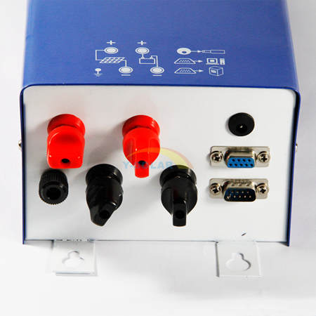
Installing dimension
We suggest installing the controller on the vertical wall, and ensure there is the space over 10cm around the controller for heat emission.
1. We suggest the user to use the sheathed cable with the cross-sectional area over 6mm2.
2. We suggest installing breaker and fuse on the negative loop of battery and solar panels.
3. Set the controller’s ground terminal to reliably connect to the system ground bus.
4. The capacity of the controller internal over voltage absorption is limited. Please make sure connect the solar panel to the controller after connecting to the mine exchange line box.


Wire & tool preparation
⑴Prepare 6 mm2 black and red sheathed cables, each one roll. Prepare several copper noses ofФ6-6mm2 since controller adopts inФ6 terminals
⑵Hydraulic pliers(for crimping copper nose and cable) and 6 mm2 die, one couple, 10mm wrench, 2 sets, Phillips screwdriver, 1 set, cutting pliers, 1set
⑶Cut the cables according to the cabling requirement. Use hydraulic and die to connect the copper nose and cables tightly, and prepare all the cables well.
Installing process
⑴If breaker is installed in the battery loop, please make the breaker open. If fuse is installed, please take out the fuse to prevent the phenomena of contact ignition.
⑵Use the prepared cables to connect the +,- polarity of battery to the battery terminals on the controller. Please make sure the connecting of the polarity is correct.
⑶Use the prepared cables to connect the solar panel output of the main convergence box to the solar panes terminals on the controller. Please make sure the connecting of the polarity is correct.
⑷Use the prepared cables to connect the ground terminals to the ground box of the system.
⑸ Insert the temperature sensor to the right place on the controller.
⑹Close the breaker of the battery loop or insert the fuse of the battery loop, if the controller LCD screen starts to show the signal, the controller will start to work. And if the LCD has no signal, please check whether the connecting of the polarity is correct, whether the connecting cables is in good condition, whether the breaker is closed, whether the fuse is inserter. Wait until the LCD has signal, and then go to next step.
⑺Close the breaker of the solar panels loop or insert the fuse of the solar panels loop, then the controller LCD screen will show the solar panels voltage. If the LCD shows the voltage is 0V, please check whether the breaker in the solar panels loop is closed.
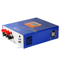
EMPPT-60 60A 12V 24V 48V Solar Charge Controller MPPT
Features
The product adopts DC/DC converting technology and MCU technology. It can adjust the working point of the solar panels array intelligently to make the solar panels array realize the maximum power output. When the external condition changes, eMPPT controller bases on the MCU theory to track the maximum working point of the solar panels, this can improve the using efficiency of the solar panels and decrease the solar generating cost. Compared with average solar charge controllers, eMPPT can improve the output efficiency of the solar panels by 5% to 30 %( the output increasing proportion affected by the factors such as the attribute of the solar panels, environmental temperature and lighting conditions). The product adopts in big screen lattice LCD, and uses the vivid icons to indicate the parameters. It has concise and vivid interface. The product is wall mounting installation. Please refer to chapter 2.1 for the installing dimensions.
 |
 |
 |
 |
Product functions
|
Functions |
instruction |
1 |
maximum power point tracking |
Adopting DC/DC converting technology and MCU technology to realize the maximum output of the solar panels |
2 |
battery reversed connection protection |
Battery polarity connecting to the controller reversely (under the condition not connecting solar panels) will not cause damage to controller. It can work normally after connecting right. |
3 |
Anti-battery reverse discharge |
When solar panels voltage is less than battery voltage, the battery will not charge to the solar panels array. |
4 |
Anti-solar panels reverse connection |
Solar panels array polarity connecting to the controller reversely will not cause damage to controller. It can work normally after connecting right |
5 |
three-stage charge control |
Bulk Absorption Float |
6 |
float charging voltage adjustable |
The users can adjust the float charging voltage within a certain scope. |
7 |
temperature compensation for float charging voltage |
Referring to the current battery temperature, take 25℃ as a benchmark, the controller will compensate the float charging voltage by -4mV/Cell/℃. For 12V battery, compensation voltage U=(t-25)*6*(-0.004)V;For 24V battery, compensation voltage U=(t-25)*12*(-0.004)V;For 48V battery, compensation voltage U=(t-25)*24*(-0.004)V |
8 |
Elevating charging voltage adjustable |
The users can adjust the elevating charging voltage within a certain scope |
9 |
solar panel input deviated from maximum power point |
When solar panel input power is over the acceptable power for the controller, the controller will make the solar panel work deviated from the maximum power to prevent itself damaged. So the controller charges the battery by rated current. |
10 |
internal overheating protection |
When the internal temperature sensor detects excessive temperature, the controller will stop working to prevent it being damaged. It will resume working again when the internal temperature drops to a certain degree. |
11 |
temperature controlling fan |
When the internal temperature sensor detects the temperature exceeding a certain degree, the controller will start the cooling fan until the temperature drops to a certain degree. |
12 |
panel over voltage protection |
When the input voltage of the solar panels exceeds the rated voltage, the controller will start protection automatically and stop working until the input voltage resumes back to the normal scope. |
13 |
remote controlling function |
This optional function can make it possible to view and set the parameters of the system on PC. |
Technical parameters
| model | eMPPT6024Z | eMPPT6048 | |
| input | solar panel input voltage scope | ≤70V | ≤130V |
| maximum power point voltage tracking scope | 12V~70V(12V) | 48V~130V | |
| 24V~70V(24V) | |||
| solar panel input route | 1 route | 1 route | |
| output | rated working voltage | 12V/24V auto switch | 48V |
| maximum charging current | 30A | 30A | |
| no load loss | ≤45mA | ≤45mA | |
| charging mode | (Bulk Absorption Float) | ||
| float charging voltage | 27.6V(adjustable) | 55.2V(adjustable) | |
| temperature compensation for float charging voltage | -4mV/cell/℃ | -4mV/cell/℃ | |
| absorption charging voltage | 28.8V(adjustable) | 57.6V(adjustable) | |
| temperature scope | -20℃~+70℃ | -20℃~+70℃ | |
| others | protection functions | ①battery reverse connection function | |
| ②battery reverse discharging function | |||
| ③solar panel reverse connection function | |||
| ④solar panel input over voltage protection | |||
| ⑤radiator overheat protection | |||
| ⑥input over power deviated from maximum power point | |||
| cooling way | thermostat active cooling | ||
| optional function | (RS485 or RS232)remote controlling function | ||
| working temperature scope | -10℃~+50℃ | ||
| working altitude | ≤3000m | ||
| working humidity scope | 0~90%,no condensation | ||
| volume | 380mm*150mm*100mm | ||
| weight | 4.5 Kg | 4.6 Kg | |
| storage temperature scope | -30℃~+80℃ | ||
Installing dimension
We suggest installing the controller on the vertical wall, and ensure there is the space over 10cm around the controller for heat emission.
1. We suggest the user to use the sheathed cable with the cross-sectional area over 6mm2.
2. We suggest installing breaker and fuse on the negative loop of battery and solar panels.
3. Set the controller’s ground terminal to reliably connect to the system ground bus.
4. The capacity of the controller internal over voltage absorption is limited. Please make sure connect the solar panel to the controller after connecting to the mine exchange line box.
Wire & tool preparation
⑴Prepare 6 mm2 black and red sheathed cables, each one roll. Prepare several copper noses ofФ6-6mm2 since controller adopts inФ6 terminals
⑵Hydraulic pliers(for crimping copper nose and cable) and 6 mm2 die, one couple, 10mm wrench, 2 sets, Phillips screwdriver, 1 set, cutting pliers, 1set
⑶Cut the cables according to the cabling requirement. Use hydraulic and die to connect the copper nose and cables tightly, and prepare all the cables well.
Installing process
⑴If breaker is installed in the battery loop, please make the breaker open. If fuse is installed, please take out the fuse to prevent the phenomena of contact ignition.
⑵Use the prepared cables to connect the +,- polarity of battery to the battery terminals on the controller. Please make sure the connecting of the polarity is correct.
⑶Use the prepared cables to connect the solar panel output of the main convergence box to the solar panes terminals on the controller. Please make sure the connecting of the polarity is correct.
⑷Use the prepared cables to connect the ground terminals to the ground box of the system.
⑸ Insert the temperature sensor to the right place on the controller.
⑹Close the breaker of the battery loop or insert the fuse of the battery loop, if the controller LCD screen starts to show the signal, the controller will start to work. And if the LCD has no signal, please check whether the connecting of the polarity is correct, whether the connecting cables is in good condition, whether the breaker is closed, whether the fuse is inserter. Wait until the LCD has signal, and then go to next step.
⑺Close the breaker of the solar panels loop or insert the fuse of the solar panels loop, then the controller LCD screen will show the solar panels voltage. If the LCD shows the voltage is 0V, please check whether the breaker in the solar panels loop is closed.
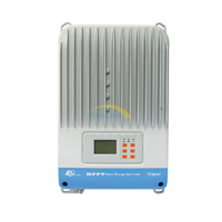
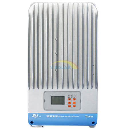
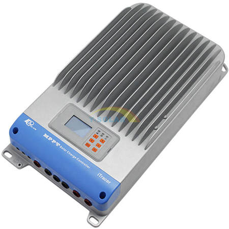
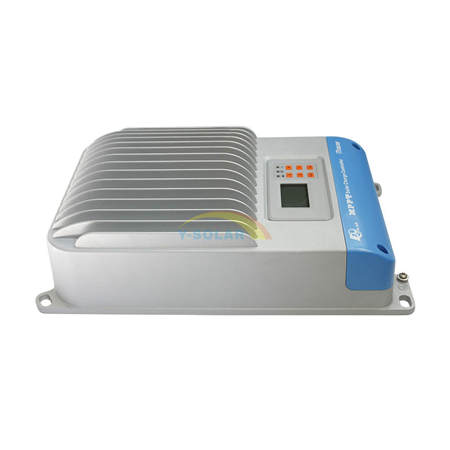
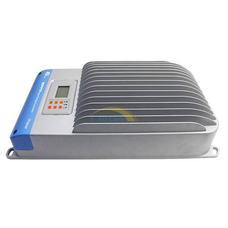
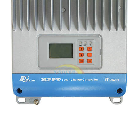
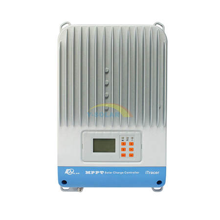
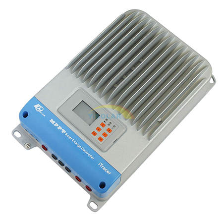
Itracer MPPT solar charge controller
Itracer3415ND,Iracer4415ND,Itracer6415ND
iTracer is an industrial grade product with advanced Maximum Power Point Tracking (MPPT) algorithm. It can deliver the maximum available power for charging batteries and charge a lower nominal voltage battery from a higher nominal voltage array.
|
 |
|
 |
 |
 |
 |
 |
Features:
Advanced MPPT algorithm with the max. tracking efficiency of 99%
Multi-phase synchronous rectification technology realizing peak conversion efficiency 98%
Dual-core(ARM CPU+DSP) control architecture improves the system response speed and optimizes the performance of the system
Multiphase control technology, optimizes charging current smoothness, reduces ripple and improves the system efficiency
128*64 dot-matrix LCD intuitively displays data and state, 6 buttons combinations for easy operation
Four battery type options: Sealed, Gel, Flooded and User-defined
Energy statistics recording, it is convenient for users to view charging and discharging energy of each day, month, year and total value.
Diversified load control mode
Programmable battery management parameters
Built-in running data and event logging, max. 15 months
Extensive communication capabilities (RS232,RS485 with Modbus protocol, CAN Bus extendable)
PC software available for real time monitoring and parameter setting
Field upgradable firmware
Electronic Protections:
PV short circuit protection
PV overvoltage protection
PV over current protection
PV reverse polarity protection
Reverse current protection at night
Over temperature protection
Battery reverse polarity protection
Load overload protection
Load short circuit protection

Model |
IT3415ND |
IT4415ND |
IT6415ND |
Rated system voltage |
12V/24V /36V/48V auto work |
||
Rated battery current |
30A |
45A |
60A |
Rated load current |
30A |
45A |
60A |
Max. PV open circuit voltage |
150V |
||
Voltage range |
8~72V |
||
Max.PV input power |
400W (12V) |
600W (12V) |
800W (12V) |
800W (24V) |
1200W (24V) |
1600W (24V) |
|
1200W (36V) |
1800W (36V) |
2400W (36V) |
|
1600W (48V) |
2400W (48V) |
3200W (48V) |
|
Self-consumption |
1.4~2.2W |
||
Equalize charging voltage |
Sealed: 14.6V, Flooded: 14.8V, User-defined: 9~17V |
||
Boost charging voltage |
Gel: 14.2V, Sealed: 14.4V, Flooded: 14.6V, User-defined: 9~17V |
||
Float charging voltage |
Gel /Sealed /Flooded: 13.8V, User-defined: 9~17V |
||
Low voltage reconnect voltage |
Gel /Sealed /Flooded: 12.6V, User-defined: 9~17V |
||
Low voltage disconnect voltage |
Gel /Sealed /Flooded: 11.1V, User-defined: 9~17V |
||
Grounding |
Common negative |
||
Tracking efficiency |
99% |
||
Peak conversion efficiency |
98% |
||
Dimension |
358x219x102mm |
382x231x107mm |
440x231x110mm |
Terminal |
25mm2 |
35mm2 |
35mm2 |
Net Weight |
3.7kg |
4.6kg |
5.9kg |
Working temperature |
-25℃~+55℃ |
||
Storage temperature range |
-30℃~+85℃ |
||
Humidity |
95% NC |
||
Enclosure |
IP20 |
||
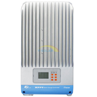
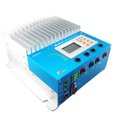
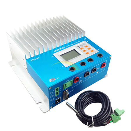
ETRACER3415,ETRACER4415,ETRACER6415
eTracer is an advanced Maximum Power Point Tracking (MPPT) controller for off-grid photovoltaic (PV) systems up to 3KW. The controller features a smart tracking algorithm that maximizes the energy harvest from the PV by rapidly finding the solar array peak power point in all the weather condition.
|
 |
|
 |

Features:
・12/24/36/48V auto work
・Advanced MPPT technology
・Several seconds tracking speed
・High Tracking efficiency of 99%
・Multiphase synchronous rectification technology
・Peak conversion efficiency of 98%
・DSP&ARM processors architecture ensures high speed and performance
・Gel, Sealed, Flooded battery option
・Max. 450 days data logging by connection to PC
・Multifunction LCD displays system data and status
・Three kinds of communication ports :RS232, CAN BUS and Ethernet
・Three stages charging optimizes battery performance
・Software update by users
Electronic Protections:
・PV short circuit protection・PV reverse polarity protection
・PV overvoltage alarm protection
・PV over current protection
・Battery overcharge protection
・Battery over discharge protection
・Battery reverse polarity protection
・Overheating protection

Model |
ET3415N |
ET4415N |
ET6415N |
Rated system voltage |
12V/24V /36V/48V auto work |
||
Rated battery current |
30A |
45A |
60A |
Max. PV open circuit voltage |
150V |
||
Voltage range |
8~72V |
||
Max.PV input power |
400W (12V) |
600W (12V) |
800W (12V) |
800W (24V) |
1200W (24V) |
1600W (24V) |
|
1200W (36V) |
1800W (36V) |
2400W (36V) |
|
1600W (48V) |
2400W (48V) |
3200W (48V) |
|
Self-consumption |
1.4~2.2W |
||
Grounding |
Negative |
||
Dimension |
231x203x105mm |
285x203x105mm |
285x203x121mm |
Terminal |
35mm2 |
35mm2 |
35mm2 |
Net Weight |
4.1kg |
4.4kg |
5.0kg |
Working temperature |
-25℃~+55℃ |
||
Storage temperature range |
-30℃~+85℃ |
||
Humidity |
10%-90% NC |
||
Enclosure |
IP20 |
||
Altitude |
≤3000m |
||
Copyright© YSmart Technology Co.,Ltd .2009-2014 Powered by Chinasolarregulator.com